|
CON1D: Heat Transfer Model of Mold, Interface and Shell
Ya Meng, Guowei Li and Brian Thomas
Continuous Casting Consortium
Introduction
Heat transfer in the continuous casting mold is governed by many complex phenomena. Liquid steel flow into the mold is directed by the angle and geometry of tundish nozzle, which affects delivery of superheat to solid/liquid interface of the growing shell. In the addition, this flow influences meniscus heat transfer, by affecting flow in the liquid powder layer, the rate of power consumption into the gap between the shell and the mold, and the formation of oscillation marks. The liquid steel solidifies against the four walls of the water-cooled copper mold, and forms a steel shell that must be thick and strong enough to contain the liquid as it is withdraw continuously from the mold.
Mold powder added to the free surface of the liquid steel melts and flows between the steel shell and the mold wall to act as a lubricant, so long as it remains liquid. In addition, the solid and liquid layers of mold flux comprise a large resistance to heat removal. Shrinkage of the steel shell away from the mold walls may generate contact resistance or air gaps, which act as a further resistance to heat flow. The latter depends on the tendency of the grade to "ripple" (forming an uneven, non-flat surface with deep oscillation marks on solidification), the strength of the shell relative to ferrostatic pressure, mold taper and mold distortion. These interfacial resistances are the most important factor controlling the rate of heat flow in the process.
Finally, the flow of cooling water through vertical slots in the copper mold withdraws the heat and controls the temperature of the copper mold walls. If the "cold face" of the mold walls becomes too hot, boiling may occur, which reduces heat transfer and makes it more variable. It is clear that many diverse phenomena simultaneously control the complex, dynamic sequence of events, which govern heat transfer in the continuous casting mold.

Model Description
A simple 1-D transient heat transfer model of the solidifying steel shell coupled with a 2-D heat conduction model of the water-cooled copper mold has been developed. Heat transfer is controlled primarily by heat conduction across the interface between the shell and the mold, which contains mold powder and air. The simple, but comprehensive, model developed in this project, CON1D, includes mass and momentum balances on the powder layers. It is being used to characterize heat transfer in a way that is consistent with experimental temperature data. The resulting equations will be used to improve the interface boundary conditions used in the advanced thermal stress models. In addition, this fast, easy-to-use model provides a tool to incorporate simplified versions of the results from other models for application in the steel plant.
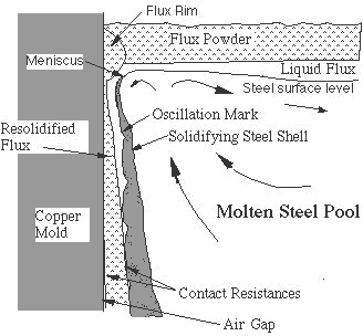
This figure shows the schematic of the side view of a top corner of the slab casting mold. Liquid steel jet inters the mold cavity through a submerged entry nozzle, and impinges on the solidifying shell. The velocity profile and the nozzle geometry influence this turbulent jet, and this turbulent flow in the mold cavity controls both of the superheat delivery from the liquid steel to the growing shell and the mold powder flow between the shell and the mold. The mold powder, acting as the lubricant, affects the interfacial heat transfer and oscillation mark formation. Other phenomena, such as the mold distortion and air gap formation make this interfacial heat transfer complicated.
 |
 |
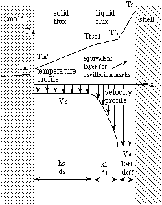
Velocity and temperature profile assumed across interfacial gap |
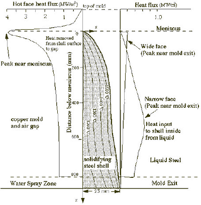
Model of solidifying steel shell showing typical isotherms and heat flux conditions |
(Click on any picture for a larger version.) |
Output Results
Fig 1 shows an example comparison between the predicted and measured temperature down the mold. The agreement suggests that the model is reasonably calibrated for typical casting conditions for the caster. This figure also shows the predicted hot face and cold face temperature profile.
The output results include the following variables (as a function of distance below the meniscus):
- Temperatures: mold hot face, cold face, shell surface and shell interior, cooling water
- Shell thickness (including positions of liquidus, solidus, and shell isotherms);
- Heat flux leaving the shell (across the interfacial mold / shell gap);
- Ideal mold taper (based on 1D shrinkage calculations);
- Thickness and velocity of solid and liquid flux layers in the mold/shell interfacial gap;
In addition, the model derives important constants: (solidus temperature, liquidus temperature, mean heat flux in the mold, heat balance at mold exit, maximum temperature in the water channel, negative strip time, oscillation mark pitch, etc.).
The model warns when there may be boiling in the water channels, if the mold cold-face temperature exceeds the water boiling point at that pressure. It also indicates when there may be excessive mold friction, if the lubricating liquid flux layer completely solidifies before mold exit.
Finally, the model outputs the temperatures of mold thermocouples, whose positions are input by the user. This allows easy calibration of the model with known data, by rerunning CON1D until the predicted mold temperatures at these positions match the measured ones.
Applications
- Parametric studies
- Boiling Prediction
- Breakout Analysis
- Lubrication Prediction
- Crack Formation Analysis
- Calculation of Ideal Mold Taper
References
B.G. Thomas, B. Ho, and G. Li, "Heat Flow Model of the Continuous Slab Casting Mold, Interface, and Shell," Report to Continuous Casting Consortium, UIUC, April 2, 1995.
B.G. Thomas, Y. Meng, G. Li, B. Ho, N. Youssef, "CON1D V. 4.1 User Manual," Report to Continuous Casting Consortium, July, 1999.
Publications:
Meng Y., and B.G. Thomas, "Heat Transfer and Solidification Model of Continuous Slab Casting: CON1D," Metalurgical and Materials Transactions, Vol 34B, No. 5, Oct., 2003, pp. 685-705. Click here for a PDF version. (844 KB)
|

