Bubble formation at Orifice with Gas Injection into Turbulent Flowing Liquid
Hua Bai and Brian Thomas
Continuous Casting Consortium
Introduction
During the process of continuous casting of steel slabs, argon gas is injected through the wall of the tundish nozzle into liquid steel stream to deter clogging with solid inclusions. It also affects the flow pattern in the nozzle, and subsequently in the mold. Analysis of defects in the final product, such as "pencil pipe" blister defects reveals the presence of argon bubbles, often combined with clusters of alumina inclusions. Argon bubble motion and its effect on flow depends greatly on the size of the bubbles, which is determined during the initial stages of injection.
This investigation was undertaken to explore the bubble formation behavior of the injected gas, with aim to predict the size, distribution and modes of the injected gas, which will provide a solid basis for the studies on bubble motion, inclusion attachment, bubble entrapment, two-phase flow in the nozzle and in the mold as well as anti-clogging techniques.

Finished work
Experiments
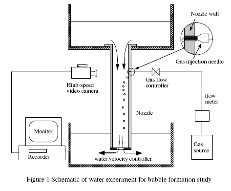
Water model experiments were performed to study the bubble formation behavior at a single and double orifices. Effects of the following parameters were tested in the experiments: gas injection rate, velocity of the flowing liquid, gas injection pore size, and gas density. Click here to see the schematic of the experimental apparatus. The main testing condition is summarized in the table below. Click here to see some of the experimental result plots.
Experiments |
| Gas injection flow rate Q |
0.17~33.3 ml/s (most < 6ml/s)
|
Average water velocity U
|
0.61~3.1 m/s
|
Gas injection pore ID d
|
0.2mm, 0.3mm and 0.4mm
|
Gas
|
air, argon, and helium
|
Nozzle size
|
35mmX35mmX600mm
|
Camera speed
|
4500 frames/s
|
The main observations:
- Bubble size increases with increasing gas injection flow rate
- Bubble size increases with decreasing transverse liquid velocity
- Bubble size in flowing system is significantly smaller than that in stagnant liquid
- Bubble size is relatively independent of gas injection pore size
- The density of the gas has little influence on bubble size
Modes of the injected gas
Besides the bubble size, another important observation is made on the mode of the injected gas. By studying the gas mode, we hope to get a better understanding of the mechanism of nozzle clogging resistance by argon injection, and the relationship between the modes and the flow patterns (such as annular flow or bubbly flow in nozzles).
Four modes were observed in our experiments. The mode is mainly dependent of the velocity of the flowing liquid, and slightly dependent of the gas flow rate. Click here to see the images of the four modes. Click here to visit my experiment video page. You can download or view the video clips of the four modes if your browser supports the QuickTime 3.
The characteristics of the four modes are briefly summarized below:
Mode I
- low liquid velocity U and small gas injection rates Q
- uniform-sized spherical bubbles
- no gas sheet along the wall.
Mode IV
- high liquid velocity U and large gas injection rates Q
- bubble elongate along the wall, forming a sheet of gas
- the sheet eventually breaks up into different size bubbles
Mode III
- special case of Mode IV, no continuous gas sheet due to insufficient gas flow Q relative to the high liquid flow
Mode II
- a transitional mode between Modes I and Mode III/IV
- elongated bubbles near the exit, but relatively uniform compared to those in Modes III and IV
The Two-Stage Model for Predicting Bubble Size
Bubble formation behavior is an extensively studied subject, especially in Chemical Engineering. However, most of the studies are about bubble formation in stagnant liquid. Few work was reported on the case similar to ours. As the first step on modeling the bubble formation behavior in our case-- gas injection into highly turbulent transverse flowing liquid, an analytical model was developed with aim to predict the bubble size.
The two-stage model is based on a sequence of events suggested by photographic observation. The bubble formation is assumed to take place in two stages, that is, the first stage or expansion stage, and the second stage or detachment stage. During the first stage the forming bubble expands while holding on the orifice, and no movement in vertical direction, In the second stage the bubble moves along with the transverse liquid stream. Click here to see the idealized sequence of bubble formation in the two-stage model.
Bubble size at the end of the expansion stage can be derived from the balance of forces acting on the growing bubble. The final bubble size (at the time of detaching from the pore) is derived from certain detaching criteria based on experimental observation. Click here to see the plot shown the comparison between the bubble sizes predicted by the two-stage model and the corresponding experimental data.
For the detailed information about the experiments and the two-stage model, please refer to the paper "Behavior of Argon Bubbles During Continuous Casting of Steel", presented at 80th Steelmaking Conference, Chicago, March, 1997, and the paper "Experimental and Theoretical Analysis of Gas Bubble Formation Behavior in Continuous Casting Nozzles", presented at 81st Steelmaking Conference, March 22~25, Toronto, Canada.
Current Work
Now, I am working on the numerical simulation of bubble formation in continuous casting nozzles. By modeling the bubble formation process, we can further explore the injected gas modes and the mechanism of anti-clogging as well as the bubble size. The commercial CFD code FLOW-3D is used in this work, which is especially strong on tracing free surface or liquid-gas interface.
Publications:
Bai. H., and B.G. Thomas, Bubble Formation During Horizontal Gas Injection into Downward Flowing Liquid, Metallurgical and Materials Transactions B, Vol. 32B, No. 6, 2001, pp. 1143-1159. Click here for a PDF version. (784 KB)
|

